The vehicle shown in Fig. 6.14 has a separate in-line hydrostatic transmission for each drive wheel. The engine delivers power via a universal joint driveline to a right-angle drive gearbox. Each side of this gearbox powers an inline hydrostatic transmission. The wheel is connected to the hydraulic motor. A final drive may or may not be used, depending on the vehicle performance criteria.
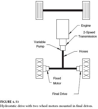

Steering of this vehicle is an issue. It will not operate like the vehicle shown in Fig. 6.13. Suppose the drive wheels are the rear wheels, and the front wheels are for steering. The swashplate controls on both pumps are set for forward travel. When the front wheels turn, both pumps continue to deliver flow for forward travel. There is no differential action. With both rear wheels powering the vehicle forward, they will tend to slide the front wheels sideways, and turning will be defeated.
A typical application for this configuration is an agricultural machine called a windrower. This machine cuts hay and rolls into a continuous pile known as a windrow. The cutting mechanism, or header, is mounted in front of the drive wheels, which are the front (forward) wheels of the machine. The back (rear) wheels are non-steered caster wheels. There is a mechanical linkage from the steering wheel to the swashplate control on both pumps. For straight-ahead travel, the swashplate on both pumps is set at the same position. When the steering wheel is turned, the control on one side is pushed forward, and the control on the other is pushed backward. One pump delivers more flow (wheel on that side turns faster), and the other pump delivers less flow (wheel on that side turns slower). If the steering wheel is turned far enough, one pump swashplate will be in the full forward position, and one will be in the full reverse position. One drive wheel turns forward, and the other turns in reverse. In effect, the vehicle “walks” itself around in a tight circle.
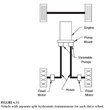
The vehicle shown in Fig. 6.15 has a separate split hydrostatic transmission for each drive wheel. It does not have the universal joint driveline or the gearbox. Power is transferred via the hoses rather than mechanically.
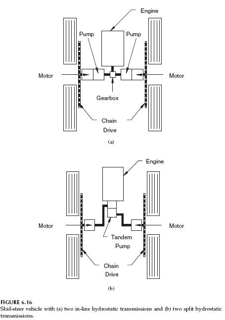
The vehicle shown in Figs. 6.16a and 6.16b is a skid-steer machine, and it is a variation of the vehicle in Figs. 6.14 and 6.15. Skid steering can be used for short-wheelbase machines. Both wheels on each side are connected with a chain drive; consequently, both wheels are powered. The machine is steered as previously described: one swashplate is shifted for forward travel, and one is shifted for reverse travel. The wheels slide as the vehicle pivots around. Typically, the swashplates are shifted with a hand lever. The operator can push one lever forward and pull the other back to pivot the machine in a tight circle.