The multiple pump design places two or more pumps in the same housing and drives them with a single input shaft. Sometimes, only one inlet is provided, but each pump has its own outlet. The advantage of a multiple pump is isolation of circuits.
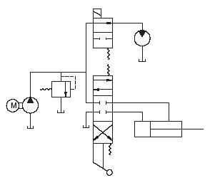
The pump shown in Fig. 4.28 supplies flow to a hydraulic motor and cylinder. When the solenoid-activated, two-position DCV is shifted, flow is directed to the motor. If the manually activated three-position DCV is then shifted, flow is diverted to the cylinder. The pressure in the motor and cylinder circuits dictates how the flow will divide. If the motor pressure is much higher, then all the flow will go to the cylinder, and the motor will stop until the three-position DCV is recentered or the cylinder reaches its full extension and the pressure builds to the pressure required by the motor circuit.
It may be undesirable to interrupt the motor operation to activate the cylinder. In this case, a multiple pump is an attractive solution (Fig. 4.29). The same electric motor is used, and all the hydraulic components are the same, except the three-position DCV now has a open center rather than a closed center. Note also that each pump has a relief valve to protect the circuit.
Gear pumps are available with more than two pumps in the same housing. No manufacturer known to the author supplies more than two piston pumps in the same housing. Two pumps in the same housing are commonly referred to as a tandem pump.

Many manufacturers of all three designs supply models with a pad for mounting a second pump on the primary pump. A cover plate is removed from this pad to reveal a splined coupling on the end of the primary pump shaft. The input shaft of the second pump mates into the splined coupling, and the bolt holes on the pad are used to bolt the second pump in place. The designer must ensure that
1. The splines match.
2. The mounting specifications match.
3. The required torque for the second pump does not exceed the rating given by the primary pump manufacturer.
It is possible to mount a tandem piston pump on the auxiliary mount of a primary piston pump and thus power three piston pumps from one prime mover. Different pump designs can be mixed. For example, a multiple gear pump can be mounted on the auxiliary mount of a piston pump.